Was Sie über das 3D-Kamera-Tracking mit Matchmover wissen sollten.
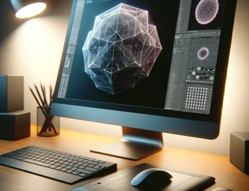
Matchmover ist eine kostenlose Software von Autodesk zum Tracken von Filmmaterial, welche in ein 3D-Paket wie 3ds Max oder Maya aufgenommen werden kann.

Tipps zum Sammeln von Filmmaterial:
- Wenn Sie das Video filmen, das Sie tracken möchten, achten Sie darauf, dass Sie hohe Kontrastpunkte haben, die die Software tracken kann – zum Beispiel einen Beitrag, den Sie auf einem Tisch notieren oder farbige Fliesen auf einem Boden. Sie müssen den Abstand zwischen diesen beiden kennen.
- Schlichte weiße Wände sind nicht gut, da es keine kontrastierenden Punkte für die Software gibt. Kacheln eignen sich gut als Ecken, an denen die Verbindung gute Gleispunkte ergibt und die Gridform ist nützlich, um ihr Koordinatensystem auszurichten. Teppiche mit geschäftigen Mustern können ein Problem sein, da sie zu viele ähnliche Muster haben, die die Software miteinander verwechseln kann.
- Wenn Sie ein Objekt, wie z.B. eine „Post-Notiz“, platzieren, müssen Sie es später entfernen. Dies kann durch Hinzufügen einer Ebene mit der Textur ihrer Oberfläche in ihrer 3ds Max-Szene erreicht werden, um den Bereich des Rohmaterials abzudecken.
- Gut ausgeleuchtete Bereiche können schwierig sein, da Farbtöne ausgebleicht werden, was die Track-Punkte schwer zu verfolgen macht.
- Halten Sie ihre Kamera während des Films ruhig. Es wird es für die Software einfacher machen, Einzelbilder zu analysieren.
- Einige Aufnahmen werden einfach nicht gut getrackt und müssen neu aufgenommen werden.
Automatisches Tracking in Matchmover.
- Matchmover kann entweder automatisch Material tracken oder Sie können es automatisch tun – das ist einfacher, kann aber je nach Material etwas länger dauern.
- Matchmover akzeptiert bestimmte Dateitypen nicht direkt, also senden Sie das Material zuerst an After Effects oder Premiere, setzen es in ein neues Compositing ein und geben es als .png-Sequenz aus. Wählen Sie keine Komprimierung in den Rendereinstellungen – sie sollen so knacking wie möglich sein.
- Gehen Sie in Matchmover zu Datei > Ladesequenz und wählen Sie die erste ihrer .png-Aufnahmen, die Sie gerade aus After Effects gemacht haben.
- Drücken Sie f10, um das Fenster „Automatic 2D Tracking“ zu öffnen. Halten Sie den Schieberegler normalerweise in der Mitte, damit es nicht zu viele Trackpunkte gibt, die Max bearbeiten kann. Natürlich wird ihre Hardware bestimmen, was die Software verarbeiten kann, also denken Sie daran.
Es kann ein paar Minuten dauern, aber Sie sollten kleine Kreuze mit grünen Schwänzen sehen, die überall auf ihrem Material erscheinen, während es getrackt wird.
Einrichten eines Koordinatensystems.
Im Moment korrelieren alle Trackpunkte mit einer 3D-Szene, aber diese Szene hat keine Skala oder Ausrichtung. Wenn wir es so importieren würden, könnte ein Stuhl wie auf dem Kopf stehend und eine Meile lang aussehen. Wir können das in Matchmover klären.
- Da wir in 3ds Max arbeiten, müssen wir am gleichen Achssystem arbeiten. Stellen Sie unter Bearbeiten > Einstellungen > Anzeige „3D Up Axis“ auf Z. Das ist die Standardeinstellung, aber überprüfen Sie sie, nur um sicher zu gehen.
- Gehen Sie zu Window > Track, um eine Zeitachse der getrackten Daten anzuzeigen. Lange grüne Linien sind gut. Grün bedeutet, dass es eine gute Strecke ist und je länger es getrackt wird, desto besser. Achten Sie auf anständige Track-Punkte mit langen grünen Zeitachsen. Notieren Sie sich ihre Ausweisnummern – der gute alte Stift und das Papier ist dafür am besten geeignet.
- Gehen Sie zu 3D-Szene > Koordinierte Ordinatensysteme. Stellen Sie den Ursprungspunkt als einen guten Trackpunkt ein.
- Sie müssen den Abstand zwischen zwei Punkten einstellen, basierend auf der Größe eines Indikators in ihrer Szene. In diesem Fall sind die Bodenfliesen beispielsweise 30 cm voneinander entfernt, also wählen Sie zwei Punkte, die dem Abstand einer Bodenfliese entsprechen, aus und geben Sie sie in das entsprechende Feld auf der rechten Seite ein.
- Als nächstes müssen Sie ihre X- und Y-Achse einrichten, indem Sie Punkte auswählen, die zu diesen Achsen in ihrer Spur passen. Finden Sie 4 Trackpunkte, die rechtwinklig zueinander stehen oder Pickpunkte, die sich rechtwinklig zu ihrem Ursprungspunkt verbinden.
- Wenn all dies erledigt ist, klicken Sie auf den Button „Koordinatensystem anwenden“, anschließend müssen Sie oben links im Footage-Viewer auf den kleinen quadratischen Button „3D“ klicken und es wird zu 2D.
- Wenn Sie eine anständige Spur erhalten und ihre Co-ords eingerichtet haben, exportieren Sie als Max-Skript (.ms-Datei) mit Einstellungen zur Animation der Kamera. Speichern Sie die Matchmover-Datei auch dann, wenn die Spur nicht so gut war, wie wir gehofft hatten, dass wir möglicherweise darauf zurückkommen müssen. Andernfalls können wir nun Matchmover herunterfahren.
- Nachdem Sie eine neue Szene in 3ds Max geöffnet haben, gehen Sie zu Max Script > Run Script und wählen Sie die gerade erstellte Szene aus. Drücken Sie C, um die Kamera zu aktivieren, die das Skript erstellt – dies ist die Kamera, von der wir rendern möchten.
Einrichten der Renderumgebung in Max.
- Stellen Sie ihren Ansichtsfensterhintergrund für das zu modellierende Quellvideo ein, indem Sie mit der rechten Maustaste auf den Text „Realistisch“ im perspektivischen Fenster klicken und auf Konfigurieren > Hintergrund > Dateien verwenden klicken und dann ihre PNG-Sequenz importieren. Aktivieren Sie das Kontrollkästchen mit der Bezeichnung „Hintergrund animieren“. Achten Sie darauf, dass Sie im Dateifenster das Kontrollkästchen Sequenz anklicken.
Als nächstes gehen Sie zu Rendering > Render SetUp > Environment und stellen Sie ihre PNG-Sequenz als Umgebung ein. Aktivieren Sie erneut das Kontrollkästchen für die Reihenfolge. Wenn Sie einen Frame rendern, wird die Umgebung möglicherweise nicht korrekt angezeigt. Dies liegt in der Regel daran, dass es standardmäßig kugelförmig ist. Um dies zu beheben, öffnen Sie ihren Materialeditor, ziehen Sie den Umgebungsplan auf einen neuen Slot und klicken Sie auf die Registerkarte Instanz in dem sich öffnenden Fenster. Stellen Sie in der Koordinateneinstellung die Zuordnung auf Bildschirm ein. Dies sollte es platt machen, damit es richtig erscheint.
Jetzt wollen wir testen, wie gut unser Track war. Erstelle eine einfache Box oder zwei und lege sie auf den Boden und rendere ein sehr kleines Video. Um alle kleinen Tracking-Punkte während der Modellierung auszublenden, gehen Sie zu „Anzeigeoptionen“ – die fünfte Registerkarte im Erstellungsfenster und aktivieren Sie „Helfer ausblenden“. Selbst bei niedriger Auflösung sollten Sie überprüfen können, ob die Modelle im Video überspringen oder ob sie richtig sitzen.
Wenn ihr Track erfolgreich war, besteht der nächste Schritt darin, HDR-Beleuchtung und detailliertere Modelle, Texturen usw. hinzuzufügen, um eine realistischere Aufnahme zu machen.
Vielen Dank für ihren Besuch.